The Tube Screamer is the most commonly copied, cloned and modified circuit in the overdrive industry. Its initial inception was unique unto itself at the time. Since then it has become a staple of every guitarist as well as sections of the circuit being built into amps.
Mods Done to this pedal
808 mod (keeley/analogman)
Keeley baked mod
Keeley mod plus
buffer upgrade Mod (mine)
clipping mod (mine)
Led Clipping switch (mine)
808 mod
You can find this mod everywhere and it is quite simple. It is 2 resistors at the output buffer and an opamp transplant. This mod is supposed to make the sound more open but in my findings there is only a few circumstances in which this pedal may benefit from an 808mod and that is if you were to run it into a low impedance pedal like a vintage fuzz face or something similar or if you have a ts9 with anything other than a 4558 opamp variant. The ts9 came in several flavors of opamps but there were quite a few horrible stock options that yours can come with. Needless to say the 4558 variant is better than a lot of cheap opamps, But for pennies to dollars you can go with way better. The TLO72 exists in the KLON Centaur and is used in quite a few circuits and also is leaps and bounds better than the 4558 variants for 17 cents in most places. In this build I went with a OPA2604. It yields a Robust distortion that doesn’t peter out at high gain settings and creates effortless highs for around 2 dollars. This site has a very good write up on the ts808 mod.
Baked mod
This mod basically changes the threshold for the gain structure. It gives you more range.
Mod Plus
All caps that are inline with audio signal are replaced with something better (poly usually)
MOSFET mod
Not really a mod. Just something I saw in a BYOC pedal. The input buffer is replaced with a MOSFET transistor with yields a livelier sound. It is the tubiest of all transistor types. After doing this mod I decided to just go with a cleaner chip (2n5088 or even a 2n3904). The MOSFET mod is too colored (in a tubey way) for my taste and quite noisy in some circumstances. A simple JFET upgrade will do.
clipping mod
This is one of mine. silicon diodes in asymmetrical configuration. Meaning that there are 2 pointed one direction and 1 pointed the other. Silicon yields a more transparent distortion in this configuration.
LED clipping switch mod
Also one of mine. You can now switch between LEDs or Diodes. This is a similar arrangement to the rock Box Boiling Point. The LED section gives you more headroom for a less compressed sound.
MODS
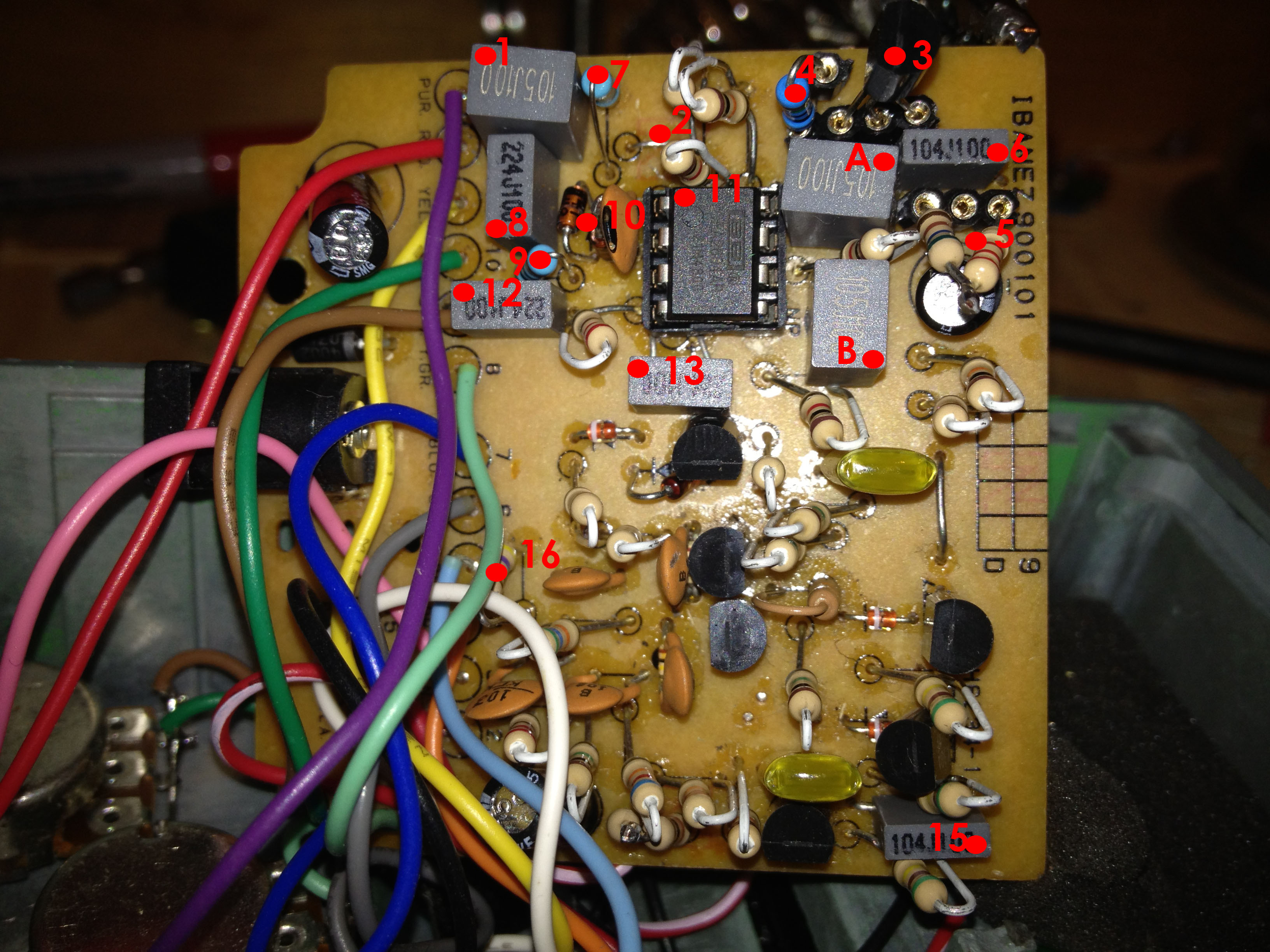
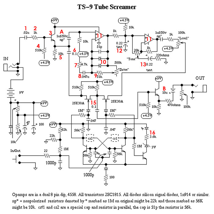
There is also a schematic at the bottom so you can print it out and follow along more effectively
diagram(item 1)
Changed from .02u to 1u. This cap doesn’t need to have this large of a value. There are no good or bad aspects otherwise. I put it there because I had it on hand.
diagram(item 2)
Removed 1k resistor. Not necessary. May have been put there because the original transistor has a high HF so it is quite hot
Please ignore mods 3, 4 and 5, They are for experimenting only and held no real value in the long run of the project.
///////////////////////////////////////////////
diagram(item 3)
2n7000. Mosfet upgrade from original transistor. Downfalls of this setup is that the pedal makes a horrible hiss if there is nothing plugged into it due the high insertion ratio. This can be fixed with a switched jack that shunts to ground.
diagram(item 4)
510k to 10M resistor for mosfet mod and back to 510k when I decided against using a MOSFET
diagram(item 5)
10k to 2.7k resistor for mosfet mod and back to 10k when I decided against using a MOSFET
///////////////////////////////////////////////
diagram(item 6 and 15)
100n replaced cheap cap with a Wima (Wima is a brand)
diagram(item 7)
changed to 1k from 4.7k.
diagram(item 8)
changed to 220n from 47n. This in conjunction with item 8 makes it so the circuit still only clips everything above the original corner frequency set by items 7 and 8 in the circuit.
diagram(item 9)
changed from 51k to 1k. This in conjunction with items 7 and 8 create the Keeley less and more mod. I dont know the exact value but I like these values. Dead clean to absolutely dirty
diagram(item 10)
I have removed the original germanium clippers for silicon diodes in asymmetrical configuration.
diagram(item 11)
They should be ashamed for putting crap chips in these pedals. I went with a hi fidelity opa2604. Along with a high slew rate the chip also has a higher gain than most other chips. It has a real robust overdrive that doesn’t peter out at high gain setting.
diagram(item 12 and 13)
220n replaced with same Wima value. These are attached to the active tone circuit. Use good parts, get good sound.
diagram(item 16)
Changed 8k to 1k. Brighter led
diagram(item A and B)
1u replaced with same Wima value. These were originally electrolytic. Using electrolytic capacitors as isolators usually leads to noise and shunting part of the sound since electrolytic are polarized(they have a negative and positive side)


